SIEMENS APOGEE SYSTEM ARCHITECTURE AND TERMINOLOGY
Apogee System and Terminology
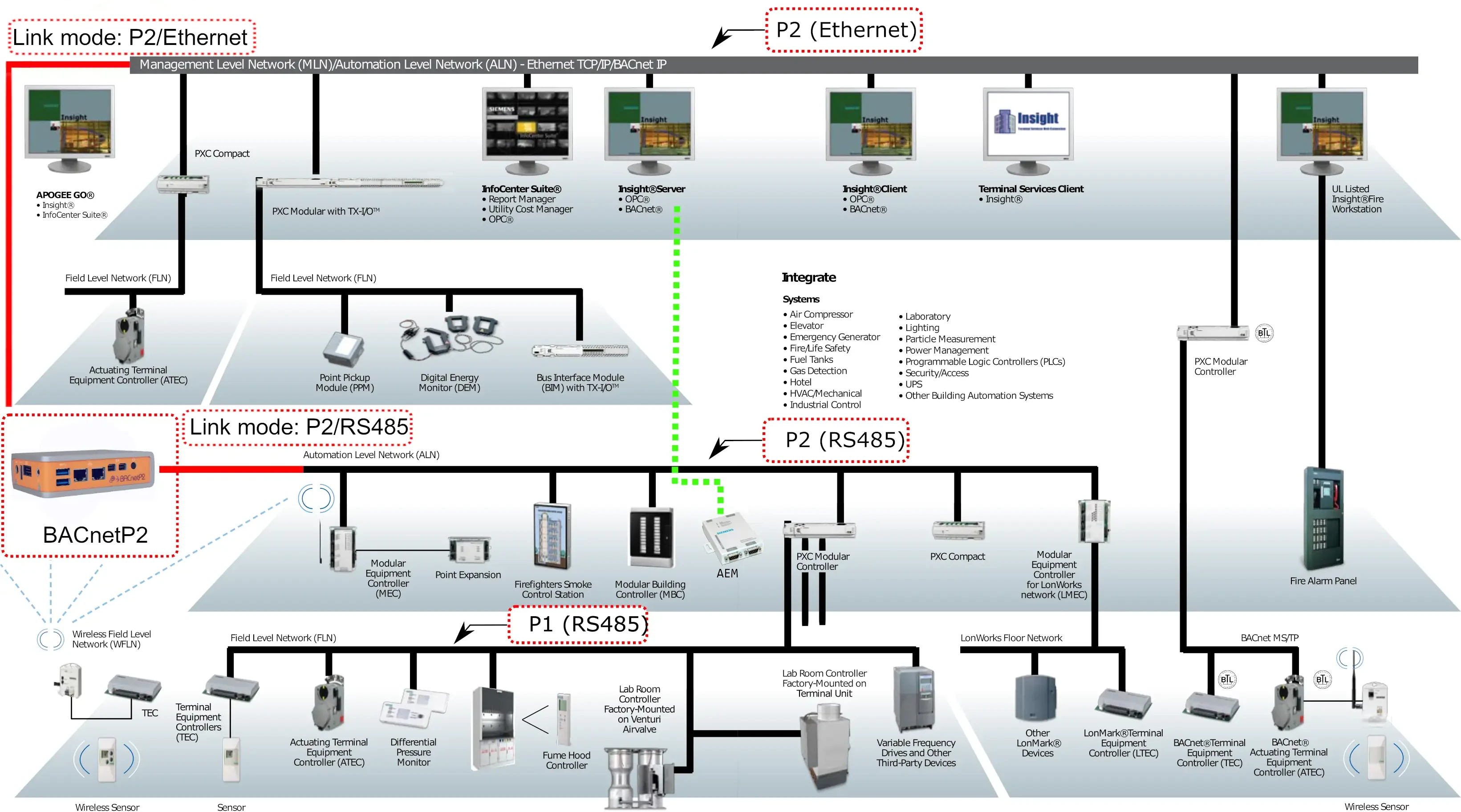
We have put this information together for you, to help you get a better understanding of the Apogee system, P1 and P2 network and Apogee terminology. We hope that you find it useful!
P1 Network
The lowest level is labeled Field Level Network (FLN) in this diagram and is a RS485 (2 wire) shielded twisted pair bus. On the older equipment the FLN was called the LAN. The FLN devices are all “subordinate” devices to the hosting controller which is the “manager”. The protocol used on this level is the P1 protocol. On a typical site most of the installed equipment runs on this FLN which is recommended to be laid out as “daisy chain” topology. The most common devices are TEC controllers with a few variable speed drives thrown in. Most of these devices run standard (canned) control application programs and will operate ON or OFFLINE from the FLN.
P2 Network
The middle level is labeled Automation Level Network (ALN) and runs the P2 protocol. On older equipment this was referred to as the BLN and was also a RS485 (2 wire) shielded twisted pair bus. On newer equipment such as some of the MEC and all of the PXC devices on this level can be run over Ethernet instead of RS485. The modular controllers are the backbone of the Siemens Apogee system. Each modular controller contains a database of virtual and physical points and can run multiple software programs written in a language called PPCL. The points in the database usually refer to physical connections on the modular controller itself and those of all the attached FLN devices that it hosts.
Insight
The graphical user interface is run on a PC and connects to the P2 network(s). Often newer ALN devices are run on Ethernet while older ALN devices connect to the PC serial port via a RS485 to RS232 converter.